Hacking Serial on a WRT — or — Voiding Warranties for Fun & Profit
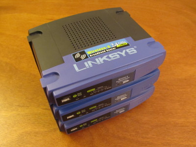
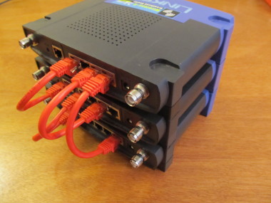
A few years ago, I picked up a handful of Linksys OpenWRT routers on ebay for a song. I made one into a wireless access point. Another formed the backbone network switch which provided VPN connectivity from living room to server room and the third was a backup for the second.
Then I tried upgrading them.
I'd rather not speculate as to what happened or why, but suffice it to say I had to buy a cheap D-link to get back on the Interwebs.
This, then, is the saga of resurrecting these devices from the brickyard, and it all starts with the need for a console. A serial console.
Turns out, the WRT devices don't have consoles. But they do have the unpopulated holes in the PCB for hooking up a serial port, which is just as good (with some soldering and a certain level of fearlessness).
First, Some Disassembly
(Note: There are much better teardown sites out there, like this one, and this one. I'm publishing this bit here primarily for my own recollection, later)
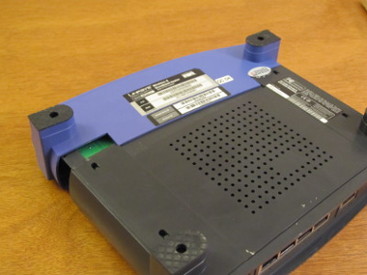
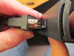
The router case is three separate pieces of plastic. The purplish-blue front piece, at least in the WRT54Gv4 and GLv1.1 units I have, is just compression fit with two tabs on the underside. It comes off with a modest amount of force. I find it helpful for new units that have never been opened to start with the corner on the left (when the unit is on its back).
If you look closely, you can see the bottom plate of the main housing separating slightly from the top (which is, confusingly enough, on the bottom, since the unit is upside-down).
With a little persuasion, we can get those two separated.
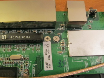
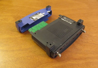
Two screws hold the mother board into the three slide clips. With those out, you can slide the motherboard down (towards you), and the board should come free. Time to solder!
Now Where Did I Leave That Serial Bus?
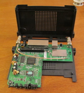
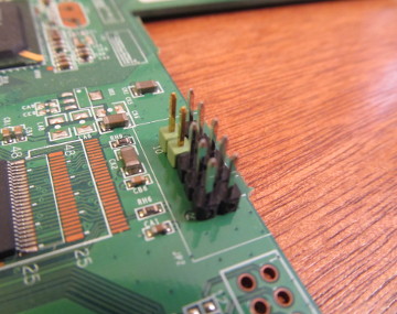
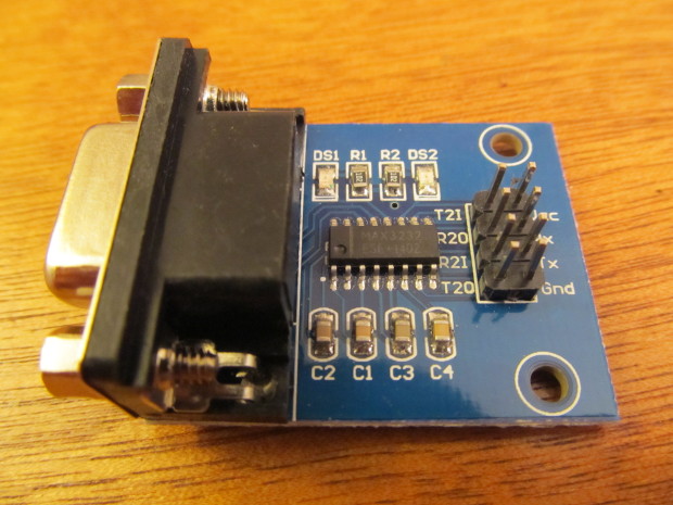
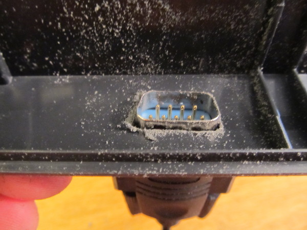
So Linksys didn't package an RS232 DB-9 serial port on the home router. You can't fault them for not wanting to confuse the unwashed masses. To their credit, they did leave us 10 pinholes for two TTL serial connections!
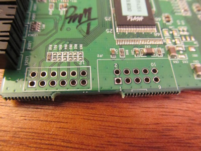
Really, there are two separate connections; the odd-numbered pins 1, 3, 5, 7 and 9 (the bottom row in the above image) form one, and the even pins form another.
First things first, let's get some headers on those empty holes!
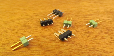
I picked these up from Mouser for next to nothing (plus shipping). I didn't realize that they would come in two- and three-header groups. I was kind of expecting one big run that I would have to break apart myself.
My wife was volunteered as my lovely assistant for this next bit. She steadied the motherboard, and held the headers in place from underneath with a pair of flat-nosed pliers. The components on the motherboard make it impossible to use the work surface to keep the pins in the holes for soldering, so another pair of hands was most useful.
I used a 40-watt soldering iron and some 63/37, .015" silver-bearing solder. I find that smaller diameters give better feed control. Too much solder is often worse than not enough!
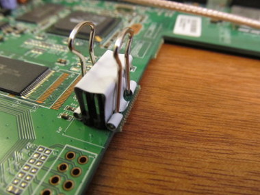
The second row went in easier than the first; I was able to use a small binder clip to clamp the loose headers to the other row. This made the piece a lot easier to move around to get the best angle on soldering.
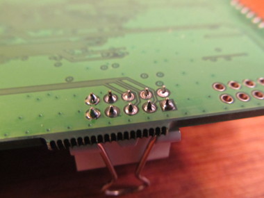
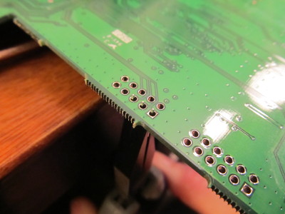
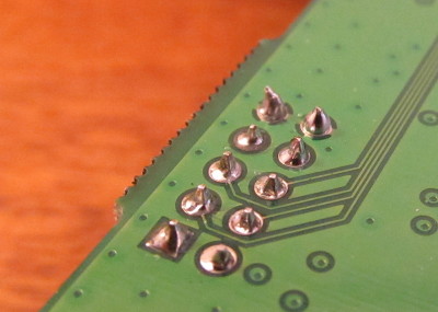
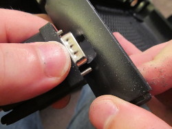
And, for those of you who may doubt my mad l33t soldering skills in the future, here's the finished product, which looks pretty good if I do say so myself:
Where There's A Tool, There's A Way
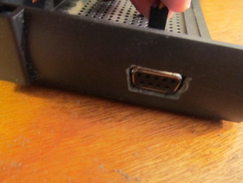
Next up, it's time to cut a hole in the case somewhere and mount the DB-9 connector and the MAX3232 upconverter chip+board. Did I mention that this is a permanent mod?
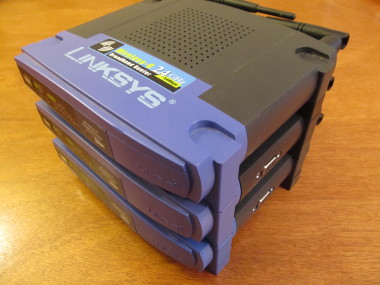
I spent hours trawling the web looking for ideas and options for mounting the serial ports. One guide mounted it on the passive air vent on top of the unit, but since I hope to stack my units, this is less than ideal. Another option was to remove the faceplate in the front and mount it there. Other people avoided the entire problem of where to put the port by just drilling a hole and running a serial cable through that.
In the end, I decided I wanted an accessible, yet unobtrusive flush-mount, on the side. Partially, this was so that I didn't ruin the aesthetic appeal of the case too much. Also, it was the only option that didn't make it difficult-slash-impossible to take the case apart again.
Most people use a Dremel multi-tool, or some other power grinder/cutting utility. I chose to cut the hole in my case by hand. While it is definitely faster with power tools, nothing beats the level of control that doing it manually gets you.
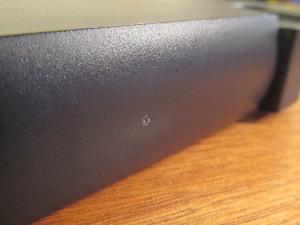
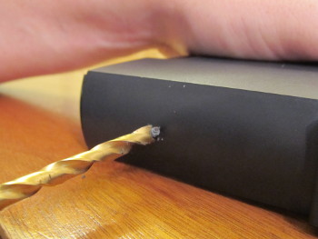
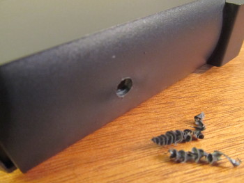
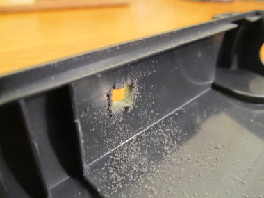
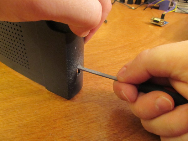
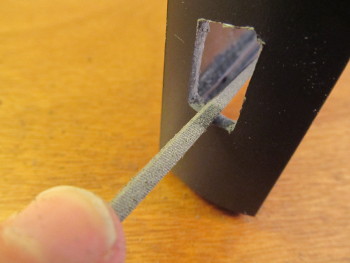
To start out, we first have to cut a hole in the side of the case. I used an old quick-change drill bit that fit into a hex-mount screwdriver. The first step is to scratch a small divot in the center of the hole:
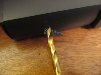
This gives the drill bit a place to rest when it starts to cut into the plastic. From here, start to slowly drill into the side of the case. At first nothing much will happen. Soon, the bit will catch and you'll start to make progress:
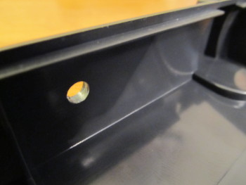
With the pilot hole drilled clean through, it's time to bring out the files:
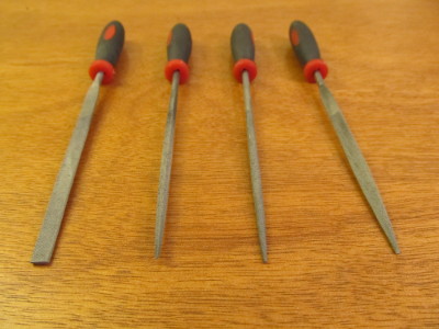
I picked these up years ago for under $10 at the local hardware store, ostensibly to do woodworking. While they're much too small for that, they work wonders on projects like this. I used three types: a flat file for removing lots of material quickly, a square file for cutting in the corners and screw-mount holes and a round file for finishing.
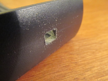
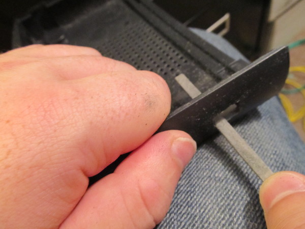
With the square file, I cut in some corners, turning the round hole left by the drill bit into a square hole just large enough to get the flat file in:
Then, I switched to the flat file to widen the hole across the depth of the case ("up" in the picture) until I got the rough size of the cut-out.
Once I was satisfied with the width of the hole, I started to expand it in the other direction, still with the flat file.
It's a good idea to periodically check the cut-out against a serial cable, since the cowl will need to fit inside the hole.
Keep expanding the cut-out until the cable fits juuust right.
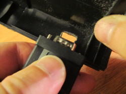
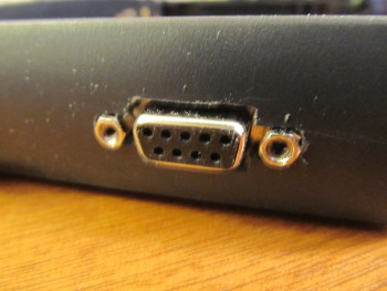
If you position the RS232 port where it is supposed to be mounted, you'll notice that we forgot the screw-holds! Switching to the square file, held on its point (more like a diamond, really), I cut the channels that they will fit into.
From here on out its just a matter of trying to dry-fit the port + serial cable, figure out what's impeding the connection and filing that bit down, until it all just fits.
Make It Stick Like Glue
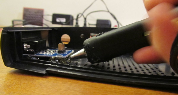
Once you're happy with the cut-out and the fit, it's time to warm up the hot glue gun and make it all real permanent.
First, however, I want to take a moment and talk about hot glue.
It's awesome.
I was skeptical at first. I toyed with the idea of running bolts through the case to steady the rear of the PCB that the DB-9 is mounted on. I tried to figure out if it was possible to be precise enough to put the screw-holds through the case to stabilize the port. I mean, how could craft glue really hold up to the stress of plugging and unplugging serial cables?
Oh it holds.
While I was taking the pictures for this article, I put too much hot glue under the chip and it squeezed out through the bottom of the cutout, between the case and the port. This made it impossible to get a good contact on the cable.
Simple enought to fix, right? Just pull the (now sacrificial) chip off the case and glue another one in. Yeah right. Getting the chip off of the hardened glue destroyed the PCB. On top of that, I had to literally chisel the glue off of the case so I could try again.
Hot glue is awesome. It's like wielding a gun full of liquid plastic. It's like a non-conductive solder. And it doesn't get hot enough to damage eletronic components.
Okay, now that you're convinced, let's start putting down some glue.
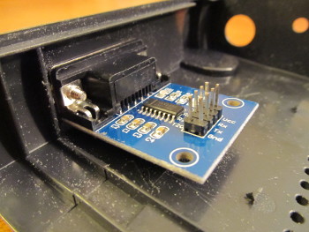
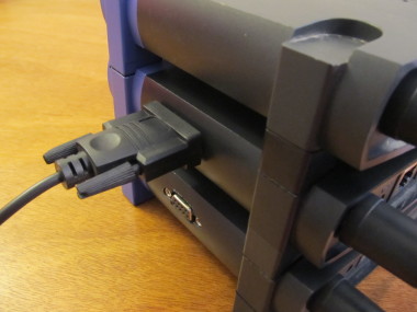
First, you're going to want to focus the glue on the end of the PCB away from the DB-9 port. Otherwise, you run the risk of ruining the whole project with some stray polymer. I strongly recommend plugging in a serial cable into the port, through the case. This will help to stabilize the card, but it also positions the connector with ample clearance on the top and sides. It's no use putting in a serial port you can't plug into!
Let the glue dry. You'll know its done with the exterior of the case, under the RS232 board, is no longer warm to the touch. Also, the chip won't move. Seriously. Try moving it. Plug that serial cable in. Do it angry! Get rough with it!!
Hooking It All Together
All parts are assembled, all connections soldered, all cases modified and all chips sufficiently glued. Time to wire it up.
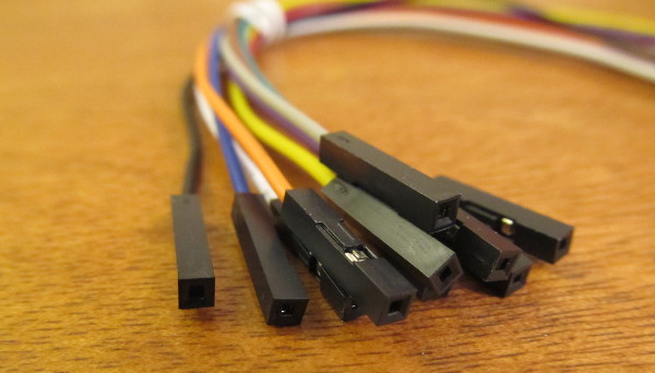
Since we soldered headers onto the motherboard, and the RS232 came with headers pre-assembled, we need female-to-female jumper wires, preferably all different colors. That means it's off to Mouser again!
First, make sure the unit is completely unplugged. If you've got the serial cable in unplug that too, just to be safe.
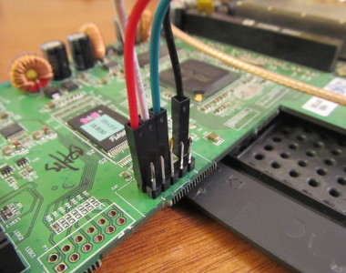
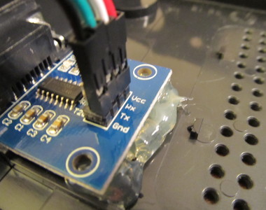
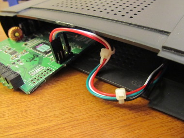
The wiring is pretty straightforward, we want to wire voltage source (Vcc) to voltage source (also, Vcc) and ground (GND) to ground (again, GND). That leaves the Rx and Tx lines. These need to be crossed, so that the Rx pin on the motherboard connects to the Tx pin on the RS232 board, and similarly, the Tx pin router-side should connect to the Rx pin on the serial port:
Or, if you prefer tables:
| JP2 | ← jumper → | RS232 |
|---|---|---|
| pin 1 | not connected | |
| pin 2 | red | Vcc |
| pin 3 | not connected | |
| pin 4 | white | Rx |
| pin 5 | not connected | |
| pin 6 | green | Tx |
| pin 7 | not connected | |
| pin 8 | not connected | |
| pin 9 | not connected | |
| pin 10 | black | GND |
It is vitally important that you get the wiring right. If you don't some bad things of varying degrees of you're-screwed-itude can happen:
- You flip Vcc and GND - VERY BAD! This will destroy your router.
- You connect to T2I/R20/R2I/T20 - BAD! While the router will continue to function, the boot serial port is dead. Those pins pass higher voltages than the TTL circuitry can handle. I know, because I actually did this with one of mine.
- You flip Rx and Tx - Annoying! No permanent damage is done, but the serial port just plain won't work. You might see a bunch of garbage binary output.
- You connect to pins 1,3,5,7,9 - Annoying! Again no permanent damage, but you are hooked up to the wrong serial port; no boot console for you!
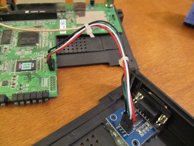
At this point, throw in some wire ties to keep things tidy and you can put the case back together. The hardware part is all done!
Dial It Up! (The Final Test)
(Strictly speaking, you really should be testing throughout the build process. As soon as I got my hands on the cable and the components, I wired it all up to verify that I had the pinouts right and that I knew how to actually use the serial port. I put the testing section last so that it was easier to find, and all in one place.)
All done with the hardware and ready to start using it? Great. Let's talk RS232.
Fun Fact: Did you know that the RS in RS232 stands for Recommended Standard? I sure didn't! Now you can wow your friends at parties!
In order to talk to our router over its shiny new serial port, you'll need the following things:
- A serial cable. Sounds easier than it is, especially when you consider that I haven't seen a laptop with a serial port in ages.
- A serial emulation program. This really is a breeze. Linux offers minicom and picocom. I'm told Windows users can use HyperTerminal.
- Configuration. How fast does the other end talk? How does it signal that its done? How big is a byte? These, and many more questions, need answers before you can talking serial.
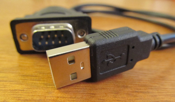
While laptops and desktops long ago dropped their vestigal DB-9 serial ports, everyone has a USB port or four. Luckily, you can pick up a USB/DB-9 serial cable for pretty cheap. Here's the one I bought off of Monoprice:
As for a serial emulation program, I tend to use picocom because it is
simple and completely command-line driven. minicom also works, although
it needs a little extra de-configuration to disable its dialing tendencies.
With those two requirements well in hand, let's turn to the last: Configuration.
With serial links, there are five (5) things you need to know:
- Line speed - How fast is the other end going to send data at
- Parity - Is the other end sending parity information to combat noise-induced errors? Is it expecting it?
- Stop bits - How many are there?
- Byte size - How big is a byte? While it's fairly well-understood, universally, that a byte is 8-bits, that wasn't always the case.
- Flow control - Is there any? Is it done in hardware (CTS+RTS or DTR+DSR), in software, or not at all?
For our purposes (and for configuring serial links to most modern devices), the answer to those questions are:
- Line speed - 115200, almost always. That's 115.2kbit/s, or around 14.4kB/s (like an old modem...)
- Parity - Nope.
- Stop bits - Always 1. Some older systems that had electro-mechanical parts sometimes used two stop bits to slow down the comm line while things moved into place.
- Byte size - 8bits to the byte.
- Software only. The console device doesn't do flow control in hardware because its complicated.
The combination of byte size, parity and number of stop bits is usually abbreviated into a three-character designation, like 8N1. The first position indicated byte size. You may see references to 7N1, which is just like 8N1 except that it only counts 7 bits to the byte. The second position indicates parity, either even (E), odd (O) or none (N). The third position identifies the number of stop bits, which in our case is 1.
So, armed with all of this newfound knowledge about ancient communication protocols, let's plug into the router serial port and fire up picocom:
$ picocom -b 115200 -e x -p n -d 8 /dev/ttyUSB0
Terminal ready


CFE version 1.0.37 for BCM947XX (32bit,SP,LE)
Build Date: Thu May 26 10:55:05 CST 2005 (root@localhost.localdomain)
Copyright (C) 2000,2001,2002,2003 Broadcom Corporation.

Initializing Arena
Initializing Devices.

No DPN
et0: Broadcom BCM47xx 10/100 Mbps Ethernet Controller 3.90.37.0
CPU type 0x29008: 200MHz
Total memory: 16384 KBytes

Total memory used by CFE:  0x80300000 - 0x803A3620 (669216)
Initialized Data:          0x80339530 - 0x8033BC40 (10000)
BSS Area:                  0x8033BC40 - 0x8033D620 (6624)
Local Heap:                0x8033D620 - 0x803A1620 (409600)
Stack Area:                0x803A1620 - 0x803A3620 (8192)
Text (code) segment:       0x80300000 - 0x80339530 (234800)
Boot area (physical):      0x003A4000 - 0x003E4000
Relocation Factor:         I:00000000 - D:00000000

Boot version: v3.6
The boot is CFE
... etc ...
It works! The Terminal ready line at the top is from picocom itself, but everything else is from the WRT router and its CFE bootloader.
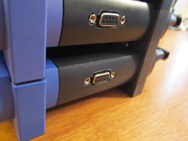
The Finished Product
Stay Tuned!
I've got a lot more to say on the subject of what you can do with a serial port on a WRT device, but this piece is drawing to a close. Keep an eye out for future posts where I hope to go over the boot process in excruciating detail, show how to get in and play around with the bootloader itself, and walk through flashing the device directly via serial+tftp. Oh, and we'll get to build our own OpenWRT images!
Happy Hacking!

James works on the Internet, spends his weekends developing new and interesting bits of software and his nights trying to make sense of research papers.
Currently exploring just how much data you can shove though DuckDB before it explodes.